Our turbidimeter uses two pulsed LEDs as light sources. The detector circuit has a band-pass filter with the same center frequency as the LED pulsing frequency or repetition frequency. Ideally this arrangement will block most of the ambient changes (lightning and temperature changes etc.) and electric disturbances (AC and digital noise, emissions of nearby electric devices etc.) outside of the center frequency. We need a clean sine wave signal whose amplitude will change according to the detected light level. But no filter is perfect, especially an analog one made of a few components.
The amplitude of the sine wave can be measured in different ways. We do it by sampling the slowly varying envelope signal of the sine wave. That is a good method since it will give stable values due its averaging nature. The downside is increased number of components.
The simplest way to pulse LEDs is to use a pulse wave from a digital output pin. LEDs will turn quickly on and quickly off with fixed interval at repetition frequency. But this is not optimal way since
- Abrupt ON-OFF changes do contain wide range of higher frequencies, not just the repetition frequency of the pulse wave. Our analog band-pass filter may not be effective enough to completely remove those high frequency components and they may deteriorate our sine wave sensor signal.
- Driving LEDs on-off with pulse wave emits a short electric pulse on each LED state change to other parts of circuit. Even though we are using good cabling (twisted pair or co-axial) and low currents, there still might be voltage noise peaks found at repetition frequency in nearby circuitry.
We would like to drive LEDs with clean sine wave. That would be ideal in many ways. But creating a good sine wave circuit is not trivial.
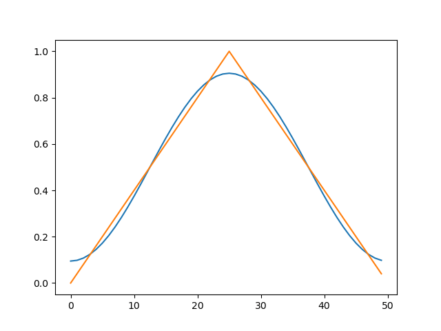
A triangle wave control signal for the LEDs is maybe the next best solution. If you compare the first Fourier series components of the triangle and the pulse you can see why the triangle is preferable.
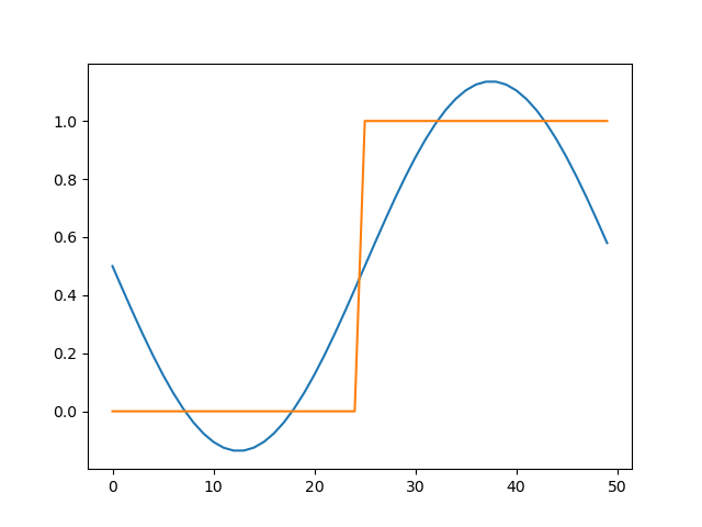
In the triangle wave the first Fourier component has nine times higher amplitude than the third component. And since the signal power is related to the amplitude squared, the first Fourier term (repetition frequency) alone already contains significant part of the total power of triangle signal.
In pulse wave the amplitude ratio is just three. The pictures here show the sine drawn on top of the triangle and the pulse wave forms to show the difference in the match.
Creating the triangular wave is straight forward. We are using a basic op-amp integrator circuit. But we need to eliminate two possible sources of error. First, the voltage driving the integrator should be stable and not sensitive to small changes of the +5V supply. Second, the temperature drift of the capacitor of the integrator should be minimized.
